HFC-227EA CLEAN AGENT FIRE EXTINGUISHING SYSTEM
HFC-227ea Fire Extinguishing System
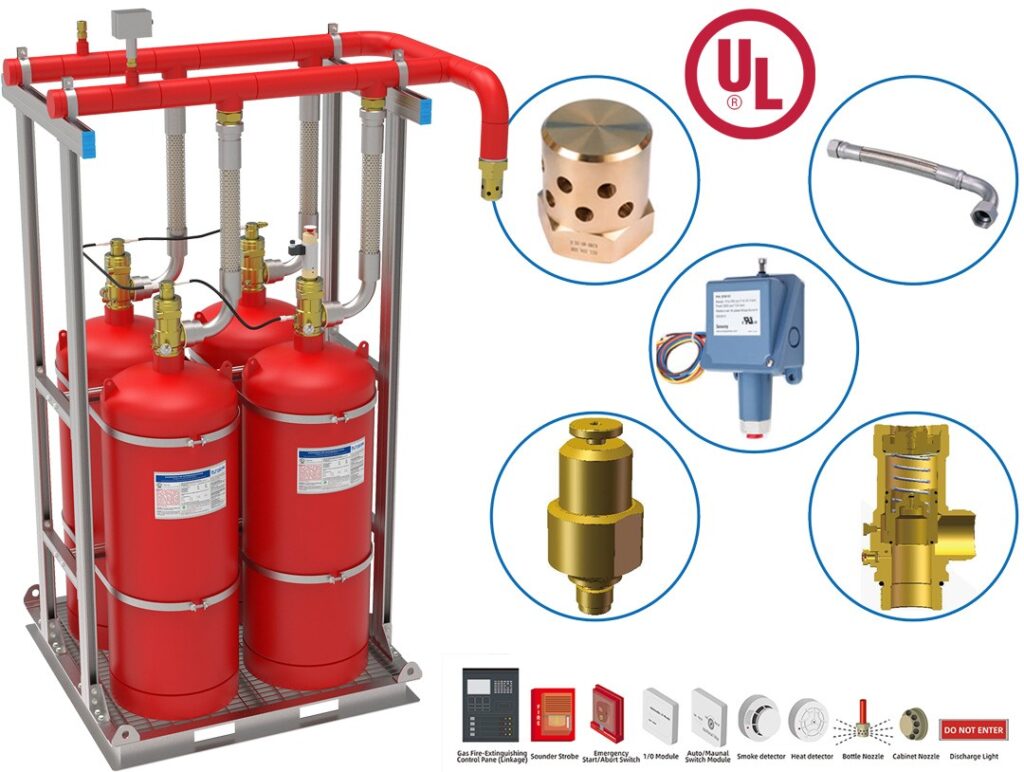
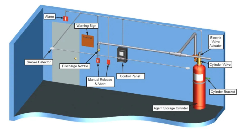
The EuroSafe Fire Systems ES Series Clean Agent Fire Extinguishing System utilizes HFC-227ea as the extinguishing medium. HFC-227ea is a colorless, non-toxic gas perfectly suited to protect high value assets in areas that may be normally occupied, in locations where clean up of other agents is problematic, when storage space for a fire suppression agent is restricted, or when an electrically non-conductive agent is required. Each system consists of the following components and their associated accessories
- Nominal Cylinder Size: 40-180 Ltr (DOT, TPED, GB)
- System Presssure: 25 Bar & 42 Bar
HFC-227ea Storage Components – Storage components consist of the cylinder assembly (s), which contains the HFC-227ea chemical agent, and the cylinder bracket(s), which holds the cylinder assembly securely in place.
HFC-227ea Distribution Components – Distribution components consist of the discharge nozzles used to introduce the HFC-227ea agent into a protected hazard along with the associated piping system used to connect the nozzles to the cylinder assembly.
Trim Components – Trim components complete the installation of the HFC-227ea system and consist of connection fittings, pressure gauge, lowpressure supervisory switch, electric valve actuator, and manual valve actuator
Slave Arrangement Components – Slave arrangement components consist of the pneumatic valve actuator(s), actuation check valve, bleed valve, pilot hose, and fittings required for a multiple cylinder (slave) arrangement.manual valve actuator.
Supplemental Components – Supplemental components include the discharge pressure switch and manifold check valve. They supplement the core equipment or complete a specific multicylinder configuration.
Control Panel – This device monitors the condition of the electric actuator, detectors, warning devices, cylinder pressure, and any manual release and abort stations. All electric or electronic devices must connect to the control panel in order to function.
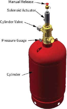
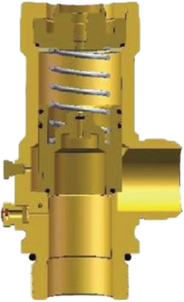
Cylinder Valve
The automatic release of HFC-227ea is controlled by a forged brass, differential pressure operated cylinder valve connected to the neck of the cylinder. The valve assembly is shipped with an anti- recoil safety device installed in the discharge outlet and chained to the cylindervalve.
Dip Tube
A threaded, rigid dip tube extends from the cylinder neck down to its bottom.
Cylinder
The light walled, welded seam cylinder is manufactured according to the requirements of TPED. Internal neck threads allow connection of the cylinder valve. The cylinder is designed for mounting in a vertical position only
Valve Actuation Connection
A threaded connection located on top of the cylinder valve serves as the attachment point for the electric (primary) or pneumatic (slave) valve actuator.
Pressure Gauge Connection
A female connection serves as the attachment point for the pressure gauge. It is fitted with an internal check valve to allow removal of the gauge while the cylinder is pressurized.
Pilot Actuation Port
A 1/4 in (8 mm) FNPT connection (shipped with a removable plug) provides a means of applying actuation pressure to the slave cylinder(s). This can also be used for attachment of the discharge pressure switch in single cylinder arrangements. The port is pressurized only during the 10 second discharge period.
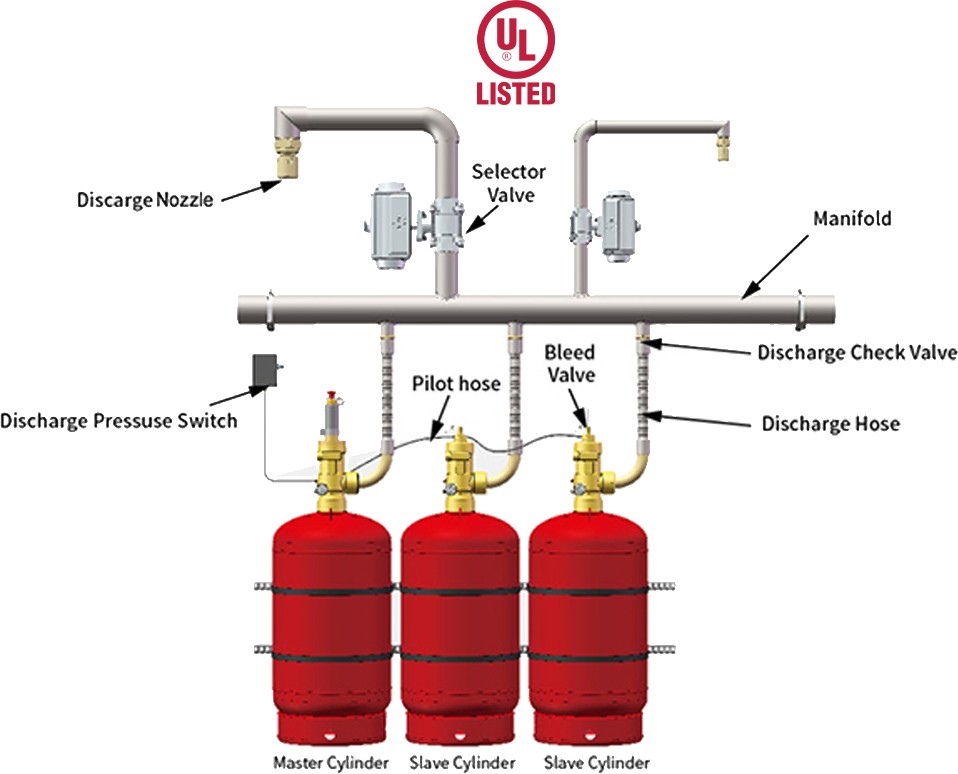
Typical ARRANGEMENT COMPONENTS
Up to 7 cylinders (1 primary and 6 slav) may be installed in a single arrangement. A typical arrangement is shown below.
HFC-227ea
Chemical Properties
HFC-227ea is formed from the elements carbon, fluorine and hydrogen (CF3CHFCF3 – heptafluoropropane). The primary extinguishing mechanism of HFC-227ea is heat absorption, with a secondary chemical contribution from the thermal decomposition of HFC- 227ea in the flame.
HFC-227ea leaves no residue and is safe for use in occupied spaces. Most common metals, such as aluminum, brass, steel, cast iron, lead, stainless steel, and copper, as well as rubber, plastic, and electronic components, are unaffected when exposed to HFC-227ea.
System
Considerations
Although the EPA Significant New Alternative Program (SNAP) lists HFC-227ea as acceptable for occupied spaces, NFPA Standard 2001 and SNAP list the following guidelines for human exposure;
The discharge of HFC-227ea into a hazard may reduce visibility for a brief period. HFC- 227ea may cause frostbite if liquid discharge or escaping vapor contacts the skin.
When HFC-227ea is exposed to temperatures greater than 1300 ° F (700° C), the by product Hydrogen Fluoride (HF) will be formed. HFC-227ea systems are designed to discharge in 10 seconds or Less in order to minimize the amount of HF formed.
The HFC-227ea Material Safety Data Sheet (MSDS) should be read and understood prior to working with the agent.
A cylinder containing HFC-227ea should be handled carefully. The anti-recoil safety device must be in place at all times when the cylinder is not connected to the discharge piping and restrained.
EUROSAFE SYSTEM ASSEMBLY
A typical EUROSAFE HFC227ea Clean Agent Fire Extinguishing System includes a gas cylinder suite, a manual discharge device, a guiding hose, an emission hose, a check valve, a manifold, a pressure-relief device, a directional valve, a pressure-operated switch, pipe fittings, a nozzle, and the units that connect the fire suppression system to an automatic fire alarm system.
Some of the components listed above may be unnecessary depending on the actual use.
TECHNICAL PARAMETERS
40L,50L,60L,70L,80L,90L,100L,120L,150L and 180Lsteel cylinders all meet the requirements of TPED.
| Material | |
|---|---|
| Carbon% | 0.200%Max |
| Manganese% | 1.500%Max |
| Phosphorus% | 0.025%Max |
| Sulphur% | 0.025%Max |
| TPED | |
|---|---|
| Hydraulic test pressure | 69.0bar(1000psi) |
| Working Pressure | 34.5bar(500psi) |
| Hydraulic test pressure | 138.0bar(2000psi) |
| Working Pressure | 69.0bar(1000psi) |
| Paint Specification | Red polyester powder Coated |
DESIGN PROCESSES OF FIRE SUPPRESSION SYSTEM
- The design of HFC 227ea system must follow the following procedures.
- Determine the hazardous substance and the required concentration.
- Determine the volume of every cabinet and take out all the impermeable volume in the right place.
- Determine the risk altitude and correction coefficient.
- Calculate the amount of HFC-227ea of every protected area at the lowest design temperature.
- Choose the type and the position of nozzles.
- Design the container size and filling density.
- Design the network of pipes.
- Calculate the amount of HFC-227ea of every nozzle.
- Check the agent percentage at every flow bypass part.
- Identify the length, rising, and declining of all pipes, and identify the nozzle reference numbers.
COST ANALYSIS
The cost of an HFC-227ea fire suppression system depends on various factors, including the size of the protected area, the complexity of the installation, and the required storage capacity. While the initial investment may be higher compared to some other systems, the benefits of quick fire suppression, minimal damage, and reduced downtime can outweigh the upfront costs in many cases. A comprehensive cost analysis should consider the long-term savings and the value of protecting critical assets.
CERTIFICATION AND STANDARD
APPLICATIONS
The HFC-227ea fire suppression system is appropriate for most commercial and industrial settings. Bank strong room, library, bookshop, electronic data processing center, telephone switching studio, communication center, transformer and switchgear room, control room, testing lab, and inflammable liquid storage room are typical areas it can protect.